Tanks that need no rescue: four layers of protection instead of endless repairs
A tank farm is the most expensive and the most vulnerable asset of an oil depot or terminal. It is also the most underestimated one in terms of industrial safety. Tanks are remembered twice: when the painting budget is planned and when something has caught fire at a neighbouring site. Between these two moments the farm lives its own life: it rusts from the inside, breathes vapours outwards, collects water on the floating roof and static charge on the nozzles.
In this article I want to look not at “how to extinguish a tank”, but at how to make sure it stops being a source of constant costs and constant risk. In recent years technologies have appeared on the market that change the very logic of operation: instead of fighting the consequences of the design, they remove the cause. Some of them we considered for our own farm, some we saw at colleagues in the industry. Here I set out what I consider important for the head of an industrial safety and occupational health function, not for a designer.
Three adversaries we fight every year
A steel tank with an external floating roof has three chronic adversaries, and all three are built into its design.
The atmosphere. Snow, rain and ultraviolet act directly on the floating roof. The roof has to move, and there is water and ice lying on it. Seals and guide-pole covers degrade in the sun within a few seasons.
Internal corrosion and losses. There is always a vapour-air mixture above the product. It escapes into the atmosphere during “large and small breathing”, condenses moisture on the metal, creates an explosive atmosphere and feeds pyrophoric deposits.
Static electricity and lightning. During loading the product accumulates a charge. A farm on an open site is a natural target for lightning. Neither factor is visible to the eye and neither shows up until it is too late.
For each of them we have an operational answer: painting, cleaning, seal repairs, resistance measurements, scheduled inspections. All of this is OPEX that never ends, because the cause stays in place.
Anatomy of floating roof failures
When we went through the defect lists for several external floating roof tanks, four points recurred time after time.
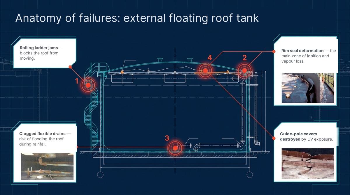
Fig. 1. Four typical failure points of an external floating roof: the rolling ladder, the rim seals, the flexible roof drains and the guide-pole covers
A jammed rolling ladder blocks the movement of the roof. What follows is either an overflow or a tilted pontoon. Deformation of the rim seals is the main zone of vapour escape and, accordingly, the main ignition zone in a lightning strike. Clogged flexible roof drains during prolonged rainfall mean a flooded roof. Destruction of the guide-pole covers under ultraviolet is a small thing that opens the way for water and vapours.
None of these points is a defect of installation or operation. It is a consequence of one structure trying to do two incompatible jobs: to protect against the weather and to contain vapours. Until these functions are separated, the defect list will keep repeating itself.
Separate the functions: a dome on top, a pontoon inside
The solution I consider fundamental sounds simple: the weather is given to one element, the vapours to another.
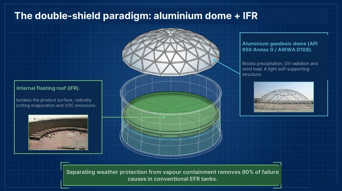
Fig. 2. An aluminium geodesic dome takes on precipitation, UV and wind. The internal pontoon isolates the product surface
An aluminium geodesic dome is a light self-supporting structure, assembled on bolts without welding and without heavy cranes. Aluminium does not corrode in our conditions and needs no painting. The dome blocks precipitation, ultraviolet and wind load. The internal pontoon under the dome works in dry conditions: it needs no drains, no covers and no protection from snow. It does exactly one thing — it covers the product surface and radically reduces evaporation.
What this gives in figures and in organisational terms is best summarised in a table.
| Conventional EFR tank | Dome + internal pontoon | |
|---|---|---|
| Service life | Limited by corrosion of the steel | Aluminium does not corrode, the service life is many times longer |
| Installation | Welding, heavy cranes, painting | Bolted joints, no special machinery, fast assembly |
| Weather vulnerability | High: snow, rain, a flooded roof | Practically eliminated |
| Usable capacity | Reduced by the roof design | Increased with the same overall dimensions |
| Hot work during installation | Mandatory | Not required |
According to suppliers’ estimates, separating the functions removes around 90% of the failure causes listed in Fig. 1. I would treat this figure as a guideline rather than a guarantee, but the principle is correct: what is not in the design cannot break.
I would like to highlight the line about hot work separately. For an operating farm this is often the decisive argument. Installation without welding means that neighbouring tanks do not have to be taken out of service and purged. For a terminal with a continuous cargo flow this is the difference between a one-month project and a one-season project.
If the tank is already old: a liner instead of a major overhaul
Not every tank survives long enough for a roof upgrade. A typical situation: the industrial safety expert review has issued a negative conclusion on the bottom or the lower shell courses, hot work on the site is banned, and the tank is needed in service within a few days. The classic answer is months out of service, welding, painting and a new expert review.
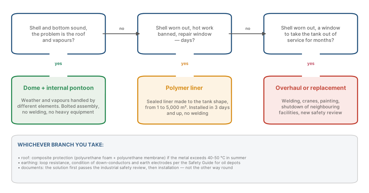
Fig. 3. Which solution to choose for a particular tank: three branches depending on the condition of the shell and the available work window
The alternative that has appeared in the industry is a polymer liner. This is a sealed shell made of PVC or thermoplastic polyurethane, manufactured individually to the shape of a particular tank, from 1 to 5,000 cubic metres. It is inserted inside and takes on the entire tightness duty. The old steel shell becomes a load-bearing structure rather than a vessel. Installation takes from three days, without welding. The declared service life is twenty years and more.
Two things matter to us. The first is legal. According to the suppliers’ experience, a tank with a liner passes the industrial safety expert review with a positive conclusion without a new set of permitting documents. This has to be checked for your own site with an expert organisation in advance, not after the installation. The second is physical, and to my mind it is more interesting.
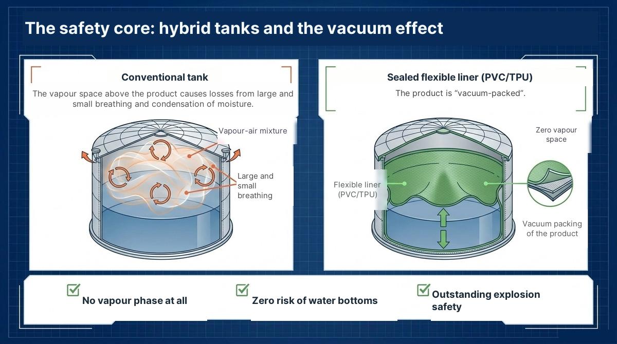
Fig. 4. Left: the vapour-air mixture above the product, breathing losses and moisture condensation. Right: the flexible liner rests on the product, there is no vapour space
The flexible liner rests on the product surface and goes down together with the level. There is no vapour space. The product is effectively vacuum-packed. Three consequences follow immediately: there is no vapour-air phase, which means no explosive atmosphere inside; there is no condensation, which means no water bottoms; there is no “breathing”, which means no losses and no emissions. For an industrial safety function this means that a whole class of scenarios from the emergency response plan simply disappears from the tank.
The fixed roof: why it ages faster than the shell
There is one more participant that is remembered less often than the roof and the bottom. It is the fixed roof and its load-bearing elements. They carry the maximum load and at the same time heat up in the sun to 60 °C in summer.
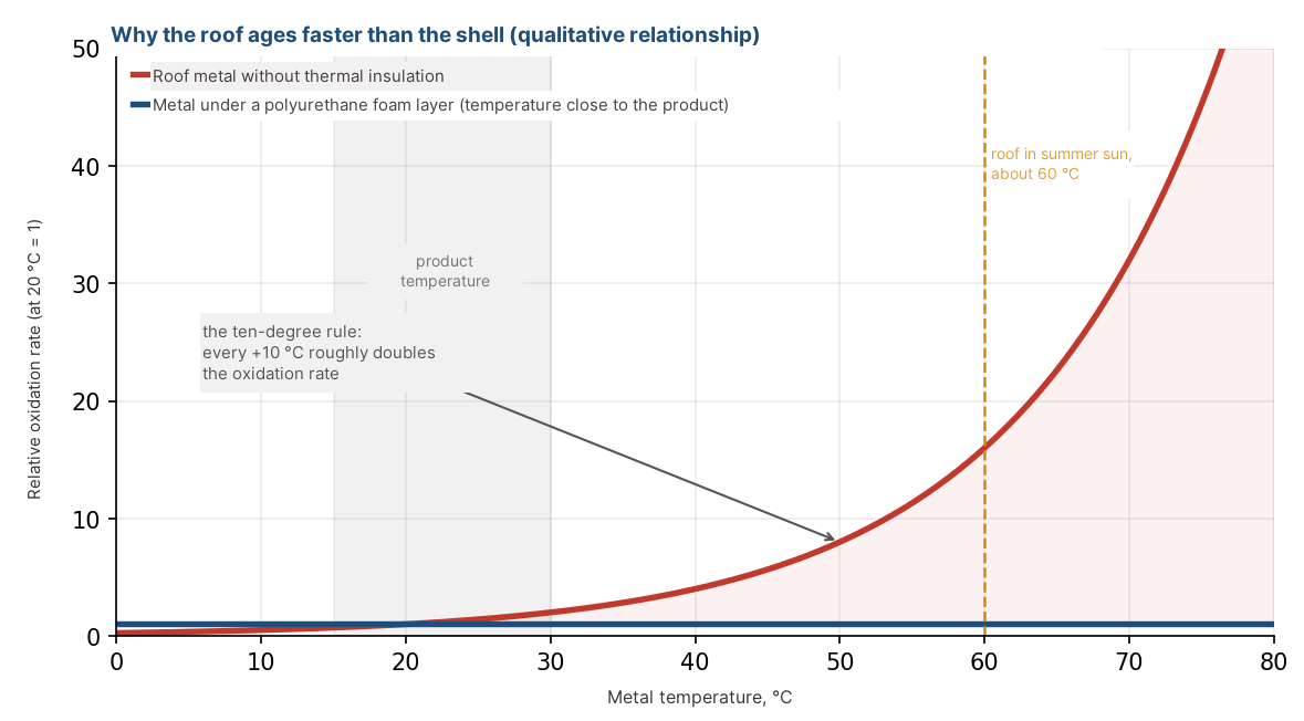
Fig. 5. The rate of metal oxidation and pyrophoric deposit formation grows exponentially with temperature. A layer of insulation keeps the roof metal close to the product temperature
The chemistry here is simple. The rate of oxidation and of pyrophoric deposit formation depends on temperature exponentially: every ten degrees roughly doubles it. Roof metal at 60 °C ages an order of magnitude faster than the shell at 20 °C. Ordinary paint does not stop this heat flow: it protects against moisture, but not against temperature.
The solution that seems right to me is composite protection of the roof.
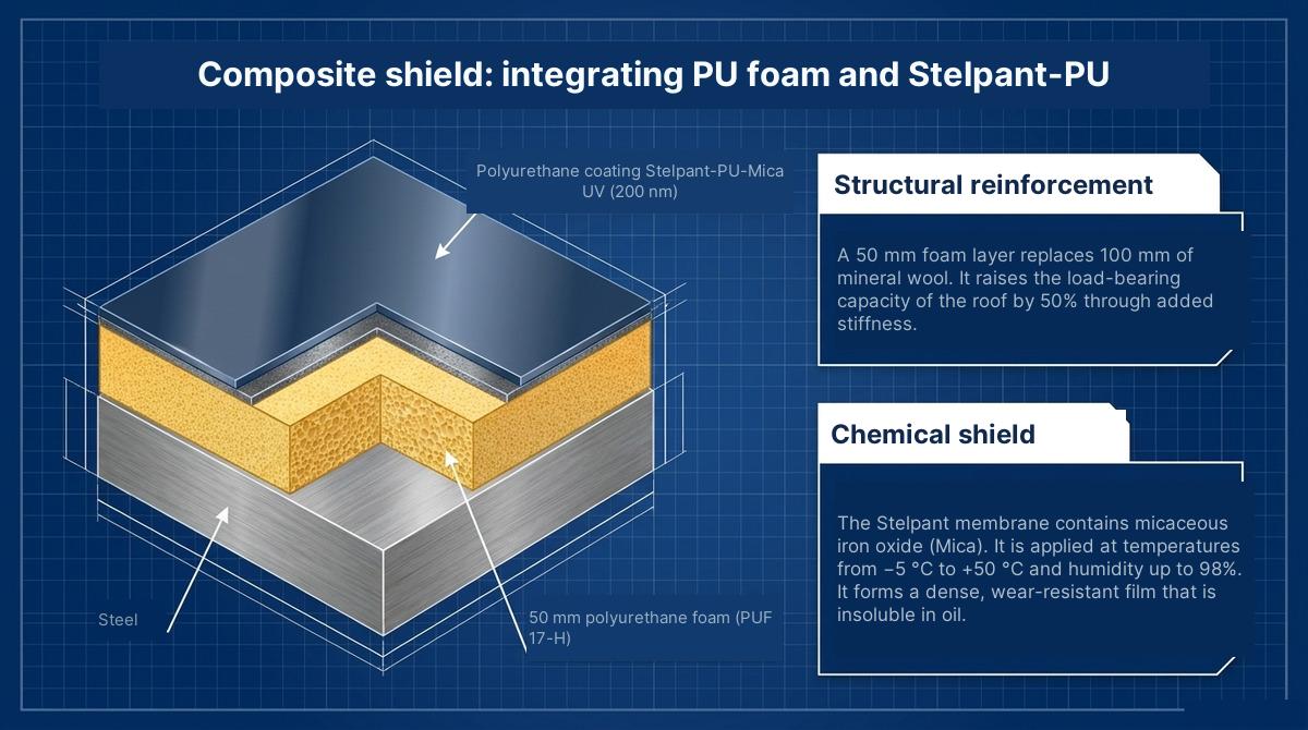
Fig. 6. The composite roof shield: steel, a 50 mm polyurethane foam layer, a polyurethane membrane with micaceous iron oxide
A 50 mm layer of rigid polyurethane foam is applied to the steel, and on top of it a polyurethane membrane with added micaceous iron oxide. In terms of thermal insulation the foam layer replaces 100 mm of mineral wool and, thanks to its stiffness, increases the load-bearing capacity of the roof by roughly half. The membrane forms a dense wear-resistant film that is insoluble in oil, and it is applied over a wide range of conditions: from minus 5 to plus 50 °C at humidity up to 98%. This means the work is not tied to a short summer window.
One technical detail worth paying attention to when choosing a contractor is the density of the foam. At a basic density of 50-60 kg/m³ polyurethane foam absorbs petroleum products. To block penetration completely you need either a top layer with a density above 80 kg/m³ or a protective enamel on top. If this point is missing from the commercial proposal, ask about it yourself. A bonus for northern sites: as the temperature drops the gas in the closed cells contracts, and the thermal insulation only gets better.
The invisible threat: static electricity and lightning
Everything discussed above concerns materials. Earthing is about procedure, and here there are two points that I would raise to the level of the head of the function.
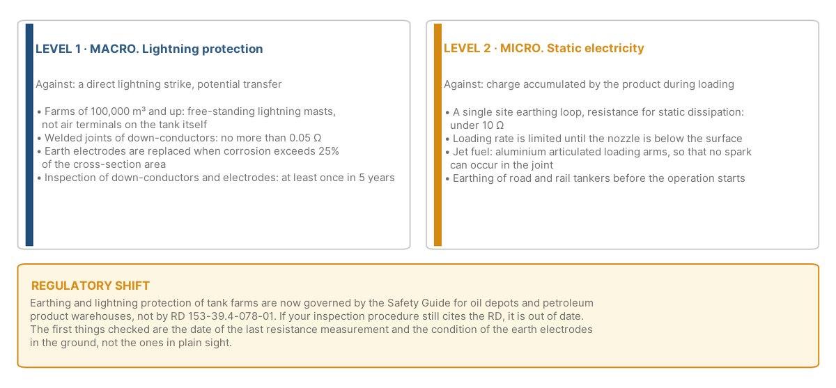
Fig. 7. Two levels of protection: lightning protection of the farm and dissipation of static electricity. The requirements are set by the Safety Guide for oil depots
The first point is a regulatory shift. Many inspection procedures at sites still refer to RD 153-39.4-078-01. The requirements in force are set by the Safety Guide for oil depots and petroleum product warehouses. If your procedure cites the RD, it is out of date, and during an inspection this will be the first finding. The Guide implies a specific inspection mandate: earth electrodes are to be replaced when corrosion exceeds 25% of the cross-section area, and down-conductors and earth electrodes are to be inspected at least once every five years. Practice shows that an earth electrode in the ground lives its own life: everything looks fine above ground, while underground the cross-section is already gone.
The second point is different levels for different threats. Lightning protection is the macro level. For farms of 100 thousand cubic metres and above you need free-standing lightning masts rather than air terminals on the tank itself. The resistance of welded joints of down-conductors must be no more than 0.05 ohm. Static electricity is the micro level. A single site earthing loop with a resistance for static dissipation below 10 ohm, earthing of road and rail tankers before the operation starts, and a limited loading rate until the nozzle is below the product surface.
A critical detail for those working with jet fuel: articulated aluminium loading arms are mandatory during loading. A steel joint can produce a spark in the connection, an aluminium one cannot. It is a small thing that costs almost nothing and that closes one of the nastiest scenarios.
How it all adds up into a system
Each of the technologies listed works on its own. But the real effect appears when they cover one another.
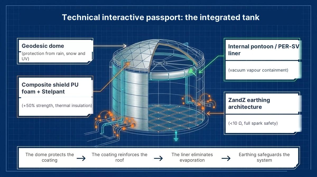
Fig. 8. The integrated tank: dome, composite roof, internal pontoon or liner, two-level earthing
The logic of the chain is as follows. The dome protects the roof coating from precipitation and ultraviolet, and the coating lasts longer. The coating holds the metal temperature and reinforces the load-bearing capacity. The pontoon or the liner removes the vapour space, and lightning has nothing left to ignite. Earthing insures the whole system in case something from the previous steps has not worked. No element replaces another, but each reduces the load on the next one.
For an industrial safety and occupational health function this changes the content of the work. Instead of the annual cycle of “painted, cleaned, replaced the seal, measured the resistance” there appears the cycle of “inspected, recorded, planned”. This is a different workload for the staff and a different risk structure in the emergency response plan.
Economics: a one-off investment versus endless costs
The first question you will be asked is how much it costs and why it is needed if the tank works anyway. I answer through the cost structure rather than through specific amounts, because every farm has its own figures.
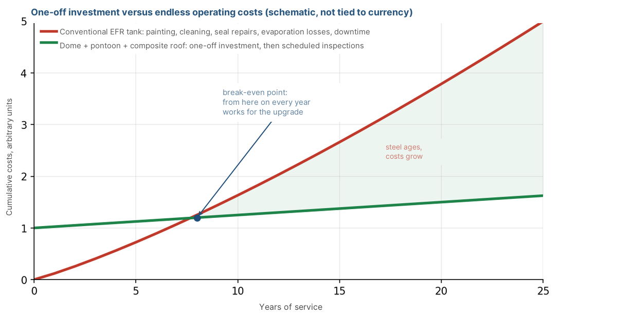
Fig. 9. A conventional tank requires growing operating costs throughout its service life. An upgraded one requires a one-off investment and scheduled inspections
For a conventional external floating roof tank the operating costs grow as the steel ages: more frequent painting, more frequent seal repairs, more downtime, and all this time the product is evaporating. For an upgraded tank the costs are concentrated at the beginning, and after that come scheduled inspections. The point where the accumulated costs become equal depends on the climate, the product and the condition of the farm, but it always exists, and beyond it every year works in favour of the upgrade.
Three figures you can use in a conversation with finance. The guaranteed service life of an upgraded tank with composite protection is 25 years and more. The amount of welding when installing domes and liners is zero, and neighbouring facilities do not stop. Emissions of the vapour-air mixture and breathing losses are close to zero. The first figure is about CAPEX, the second about the terminal’s lost revenue, and the third about environmental charges and about the fact that every cubic metre of evaporated product has also been paid for by someone.
I advise starting not with the full package. Take one tank with the longest defect list, calculate its annual OPEX over three years and compare it with a proposal for a dome and a pontoon. This is usually enough for the budget conversation to move from “why” to “in what order”.
Check yourself
- Which document does your inspection procedure for earthing devices refer to: the Safety Guide for oil depots, the Federal Safety Rules or RD 153-39.4-078-01?
- When was the last time an earth electrode was dug up in the ground, rather than the resistance simply being measured from above?
- How many times in the past three years has water stood on the floating roof after rainfall, and is that in the log?
- What is the temperature of the roof metal at noon in July? If nobody has measured it, assume around 60 °C.
- Does the emergency response plan contain a “flooded floating roof” scenario, and who acts on it at night?
- If the expert review issues a negative conclusion on the bottom tomorrow, how many days will the tank be out of service and is there a plan B?
- Are articulated loading arms made of aluminium or of steel used when loading jet fuel?
- What share of the annual farm budget goes to repeated work that removes the consequence rather than the cause?
Conclusion
A tank farm is not a sentence to endless repairs. The technologies I have listed are not exotic: domes and internal pontoons have been standing at sites for many years, liners and composite coatings are used at operating terminals, and the earthing requirements are written in the Guide, which is mandatory for everyone. There is only one new thing here — looking at the tank as a system in which every layer of protection takes the load off the next one.
The task of an industrial safety function is not only to react to an incident, but also to remove from the facility the causes that make the incident possible. A tank without a vapour space, without water on the roof and with sound earthing is a tank that simply has fewer ways to catch fire. That is exactly what I call risk management.
The technical characteristics of the solutions (a dome to API 650 Annex G / AWWA D108, polymer liners, composite roof coatings, earthing requirements) are given according to manufacturers’ data and the Safety Guide for oil depots and petroleum product warehouses in force. The choice of a particular solution for a facility requires an industrial safety expert review.